1. Before installation, please make clean both shafts, as well as hub bores, to make sure they are free of dust and burrs.
Clean and de-burrs are necessary. Measure the bore and shaft diameters to assure proper fit.
2. In terms of BE(Between Shaft Ends), please refer to the dimension chart “G” or “D” amount. (Tolerance is ±0.25mm)
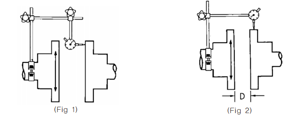
3. Check Alignment – Angular misalignment: Rigidly mount a dial indicator on one hub and place indicator on the face
of the other hub. Rotate both shafts together one revolution noting minimum and maximum dial indicator readings
(Fig. 1). In order to minimize the value, the difference of these values should not exceed as mentioned on Table 1.
4. Check Alignment – Parallel misalignment: Rigidly mount a dial indicator on one hub and place indicator on the other
hub flange outside diameter. Rotate both shafts together one revolution noting minimum and maximum dial indicator
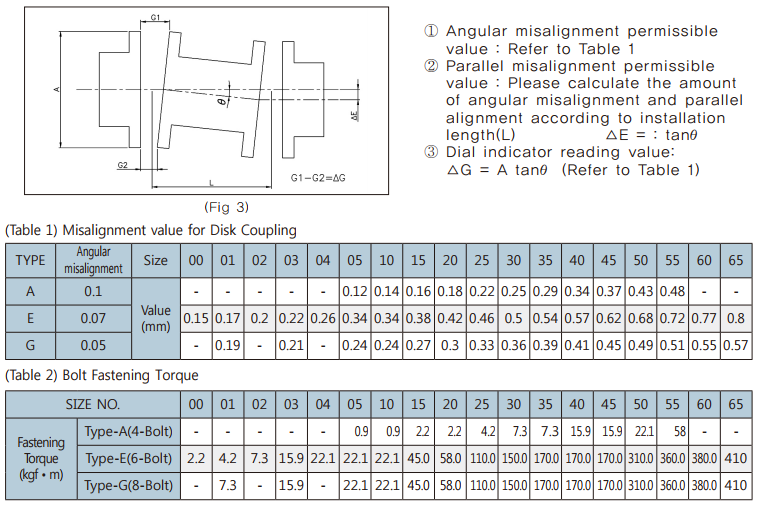
readings. After checking the parallel misalignment, find the value of △G as shown on Fig. 3 and the difference of these
values should not exceed as mentioned on Table 1 value specified in the manufacturer’s installation guide.
5. After checking alignment, please assemble spacer and element into the hubs. And insert bolt thru the hubs, spacer
and element adaptor holes. Please tighten the bolt sets to the torque listed on the Table 2.
6. For its long lifespan, we recommend you to recheck final alignment again, within 2 hours from initial operation. In case
of assemble and disassemble, we recommend you to try within 10 times.
7. You may refer to below data during installation.


